The secondary slide has to rotate on the primary slide, plus provide
the final post for holding your cutting bits. You can do a post like I
have here, or use cold-rolled steel flats to make T-slots.
My goal was to keep the compound-slide as low-profile as possible,
so the final product has plenty of room to move in under my working
piece.
|

|
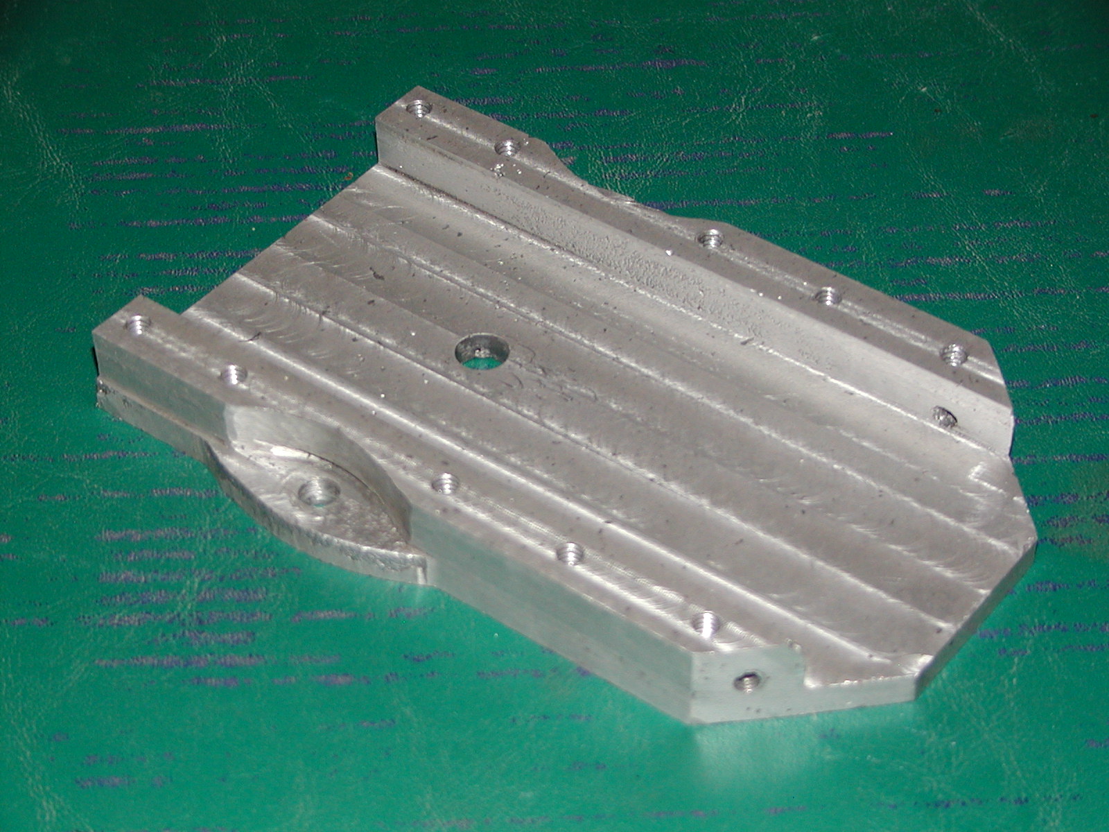
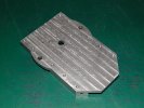
The base of the secondary slide. The top functions the same as the top of
the primary slide, although this piece is a bit shorter. Note the 'ears'
on each side. These provide the support for the set-screws on the pivot
(the circular table seen on top of the primary slide).
|
|
Bottom of the secondary slide. Since this sits on top of the pivot, it is
ground smooth. The center hole sits on the pivot pin from the primary
slide, and the set-screws prevent the secondary table from coming off.
|
|
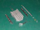
All the pieces of the secondary slide base. Front and rear feed-screw
brackets are similar to the primary. The cold-rolled steel ways have a
slot cut in the
sides to allow easy access to the pivot set-screws. The feed screw is
once again 7/16-20 thread with the front end cut to 3/8-16, the back cut
to a smooth 3/8", brass washers as thrust surfaces, and the warped
spring-steel washer to take up the slop.
|
|
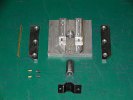
Secondary table and all it's parts. This image details all of the pieces
used in the construction of both the primary and secondary tables. The
brass piece on the right provides a wear surface for sliding the table,
otherwise it would be wearing the aluminum against a steel surface.
The brass gib is positioned under the CRS slide.
Note that nothing actually holds the gib in place except the indents for
the pins. When the table is taken completely off the base, the gib falls
out, and both pins can be lost if not careful.
|
|
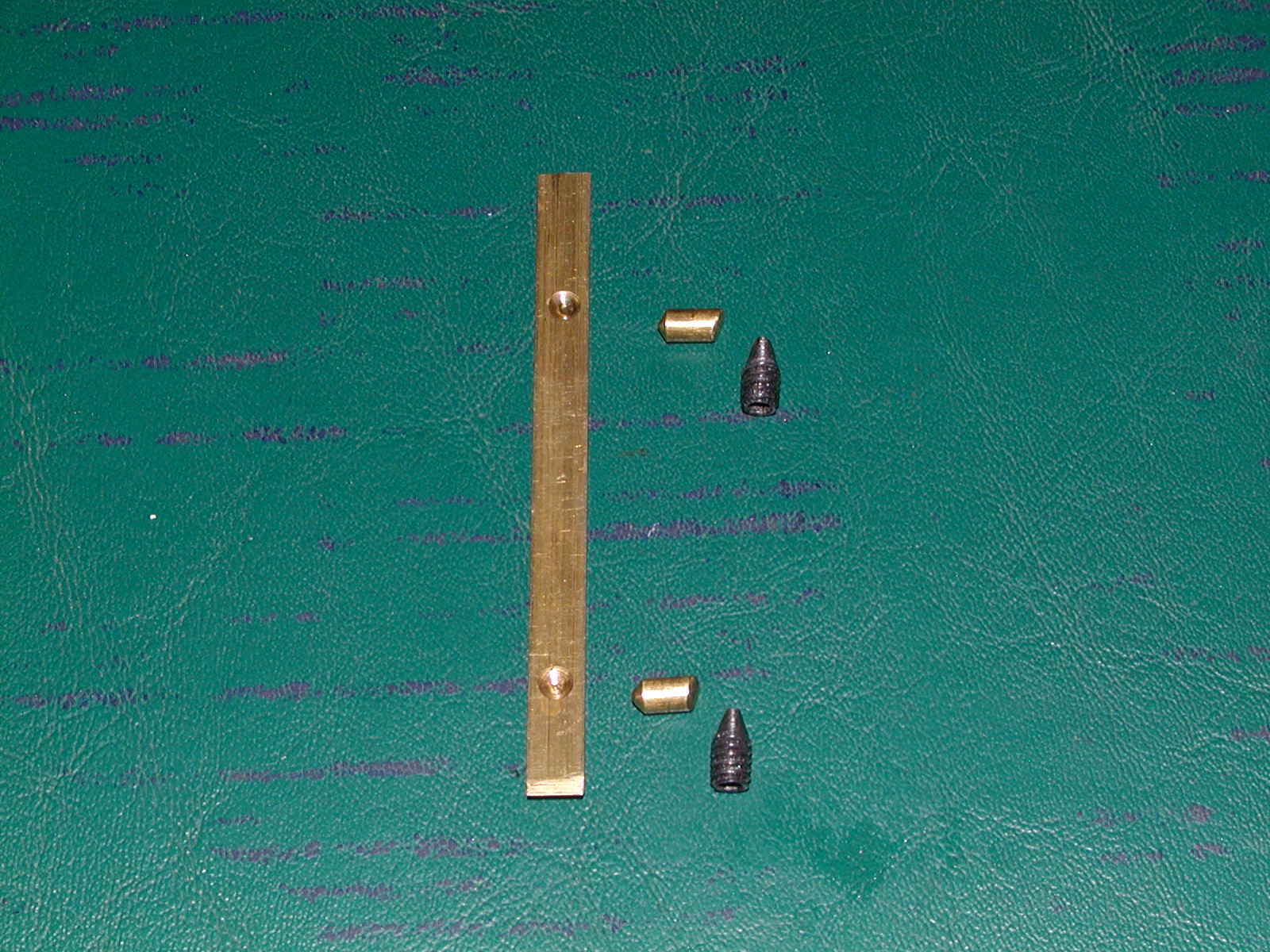
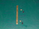
This picture and the previous show the construction of the gib and
adjustment screws. Because of the way these slides work, there would be
no easy way to adjust the gib as the screws would have to be inside the
ways. Using the 30-degree angle cut into the brass pins, and a matching
60-degree angle cut into the set-screws, very fine control of the gib
can be had from the top side of the slide tables. The set screws are
screwed down from the top of the table (see below) until they engage the
brass pins. These pins were cut and ground to length so they just start
to contact the gib. As the set-screw is screwed down further, the pins
continue to push out on the gib, until the desired setting is reached.
|

|
A view of the underside of the table. The cut grooves are for the thin
steel that holds the feed-screw nut in place. The pins fix the position of
both the holder, and the CRS slides.
Also note the extra two holes in the side, and the threaded holes
directly over them. These are for the gib adjustment screws and brass
pins. The threaded holes go all the way through to the top of the table,
which the smooth holes in the side only need to go into the threaded
hole.
|

|
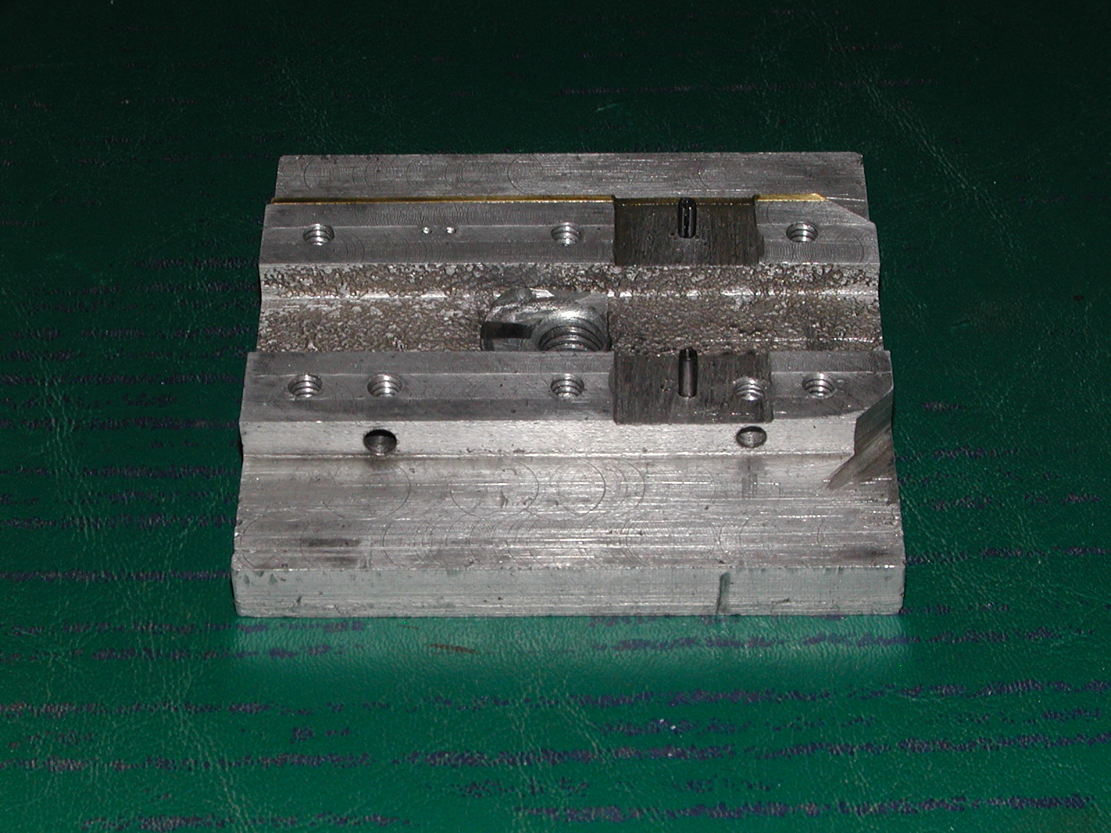
Another image showing how the steel sheetmetal holds the feed nut in
place. I made the bracket from some scrap spring-steel, and fit it so
there is a gap between it and the aluminum. When the CRS is bolted down
on top of the bracket, it forces the spring-steel around the nut,
pinching the nut so it cannot move.
|

|
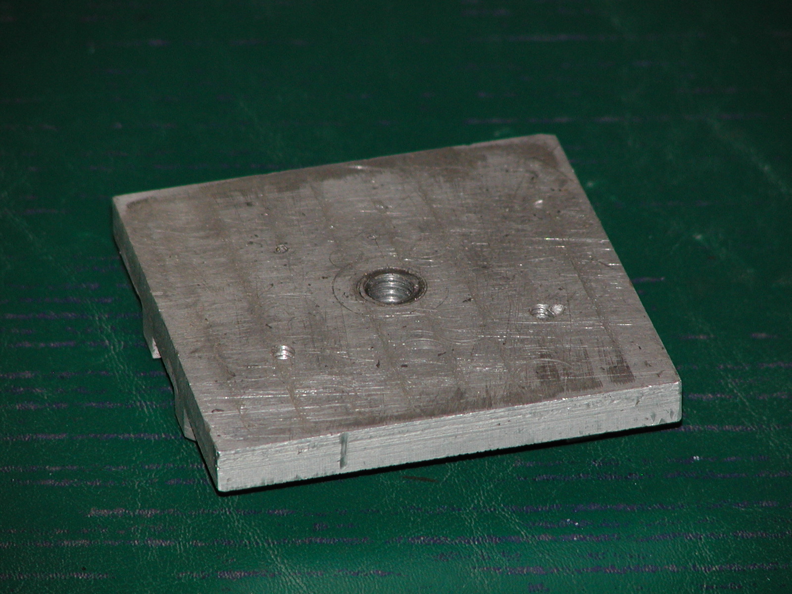
The top side of the table. Here you can see the two threaded holes for
the gib adjust screws. Also note the center hole, which is a 1/2-13
steel T-nut used to attach the lathe cutting bits. The bottom of the
T-nut can be seen in the previous images.
|

|
|
|
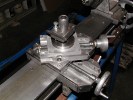
The fully assembled compound cross-slide. The tool post was made from a
lucky find, a piece of turned steel which I bored out larger at the top
to take the allen-bolt. This screws down solid to the table, and provides
the pivot point for any tool holders I make.
The tool holder shown here was cut from a piece of 3/4" thick steel.
I started by cutting a 1" hole in the center to fit on the post. A slot
was cut from the far side to the center, then a hole drilled all the way
through the slot from front to rear to accomodate an allen-bolt. When
this bolt is tightened, it pinches the holder around the post, locking
its position. Then I cut the slot that the cutting bits sit in, tapped
a couple of set-screws to hold the bits, and tapped the vertical hold in
front for a bolt to set the height of the tool holder. I have also made
similar holders for boring bars and cut-off bits.
|