Due to problems with the original cross slide design, I decided to build
a new cross-slide from scratch. The focus was on much-improved rigidity,
a lower profile, and full travel for the capacity of the lathe. Since I
still had access to a mill, I used that to design some custom pieces,
including the circular slots for the primary pivot point.
|
|
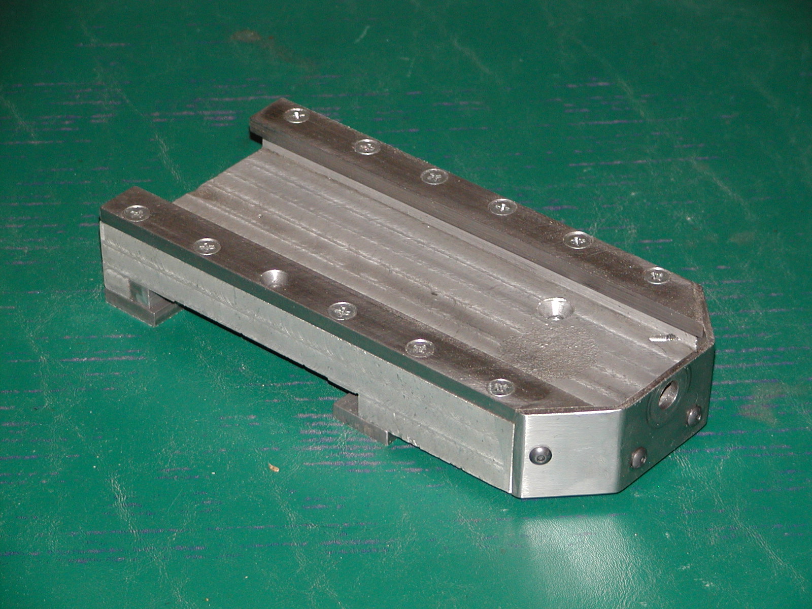
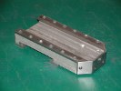
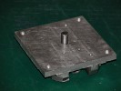
Cross-slide base. This is what everything else relies on for rigidity.
The piece is 4" wide to match the ways, providing a much broader surface
for support against deflection.
The slides are made of 1" wide cold-rolled steel. The front steel plate
is made of some scrap that I bent in the vise and filed to fit. This plate
holds the front of the feed-screw.
|
|
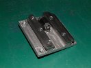
The underside has been milled to only contact the ways plate at the
front and back edges, directly under the cold-rolled steel plates. The
center is milled only slightly higher, enough to not put any pressure on
that area, but still retain the thickness and strength of the piece.
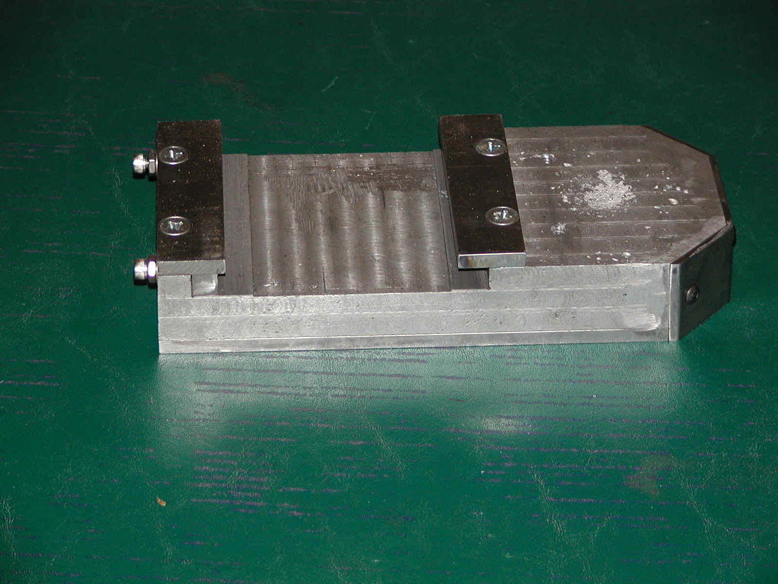
The gib is a piece of 3/8" square key stock, filed smooth for proper fit.
I started using allen bolts for the gib screws, as they made it easier to
do fine adjustments.
|

|
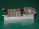
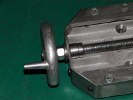
The back plate also holds the feed screw in position. It is screwed down
tightly to the base, then the thumbscrew goes through it, is threaded into
the base, and is used to lock the gib.
|
|
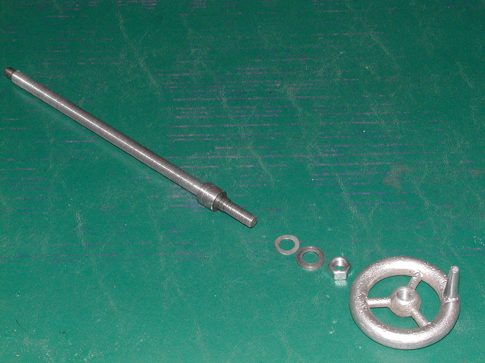
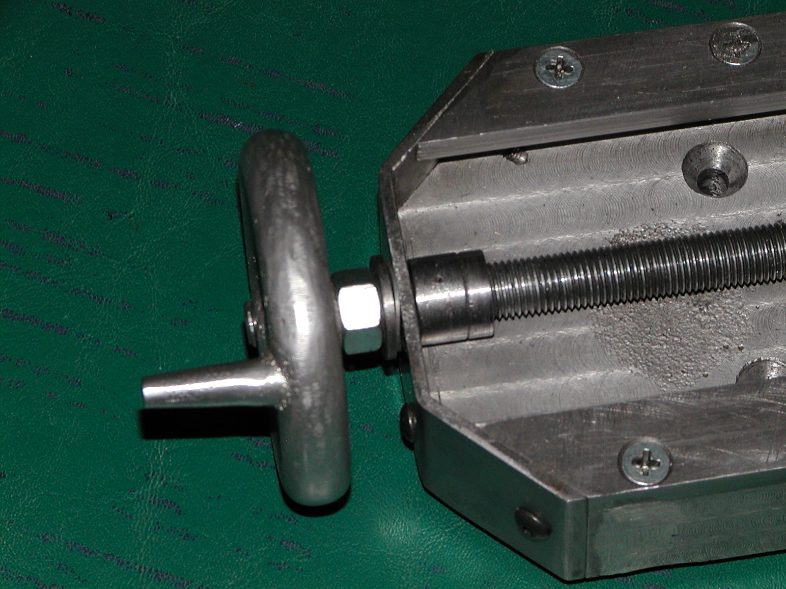
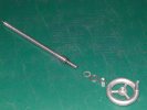
The primary feed screw. Note the warped washer at the end. This is made
from spring-steel, and provides an easy way to eliminate backlash. The
threaded rod is 7/16-20. Ideally you would use a left-hand thread for
this, but I couldn't find any at the time. The front end was cut down to
3/8-16 so I could re-use the handle from the original cross-slide. The
back of the rod is cut to a smooth 3/8" to fit the back plate.
|
|
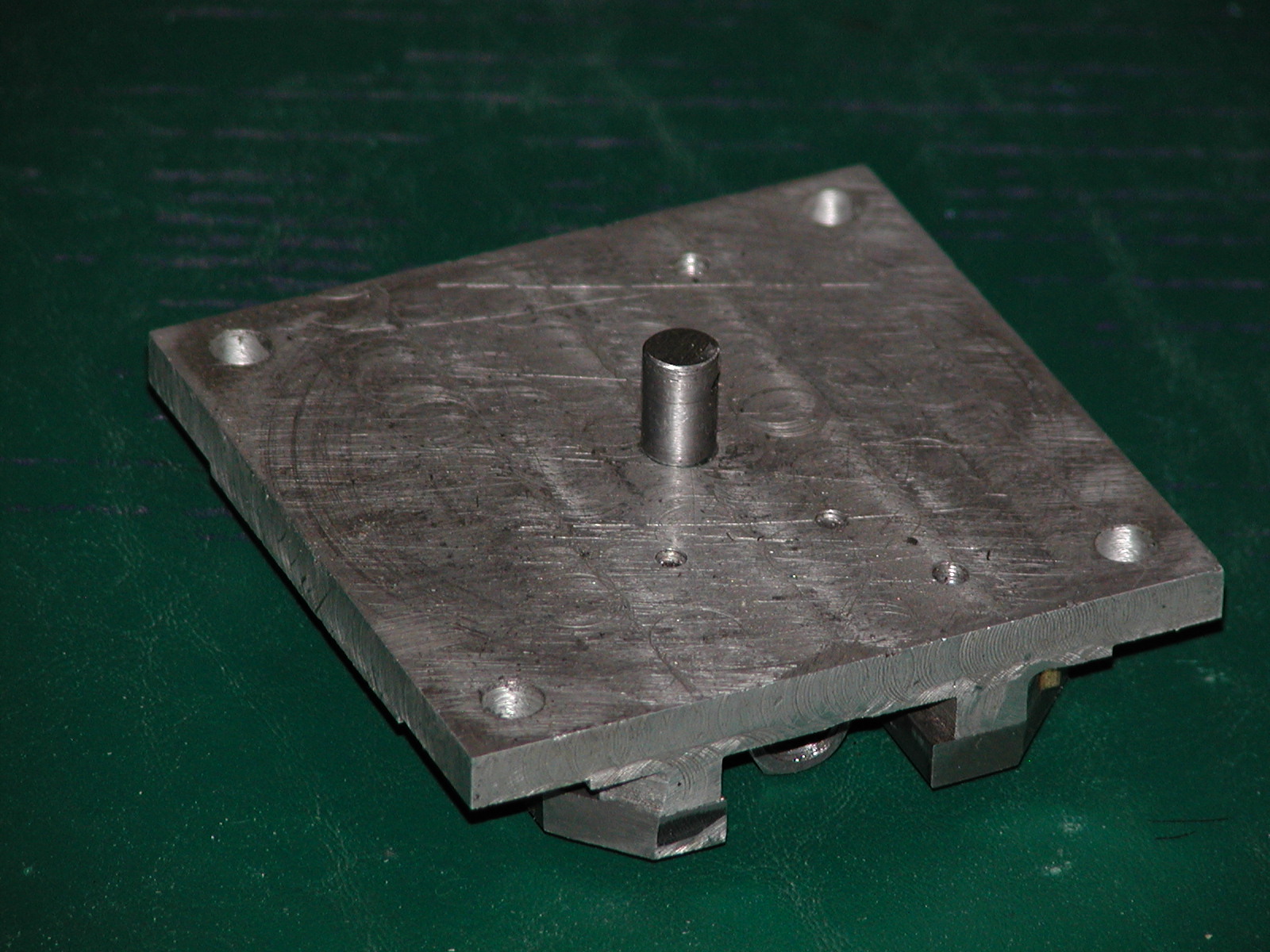
The primary slide plate. This is 4"x4" aluminum, with more CRS for the
slides. The center pin goes into the base of the secondary slide, and
provides the pivot point for rotation.
|
|
A coupling nut is mounted to the underside for the feed-screw. Because of
the length of the nut, there is almost no slop in the movement.
See the page on the secondary slide for details on how everything is
bolted down.
|
|
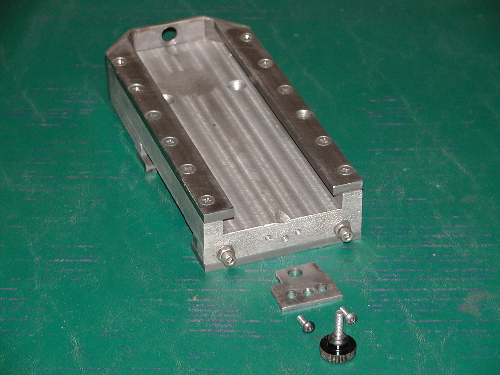
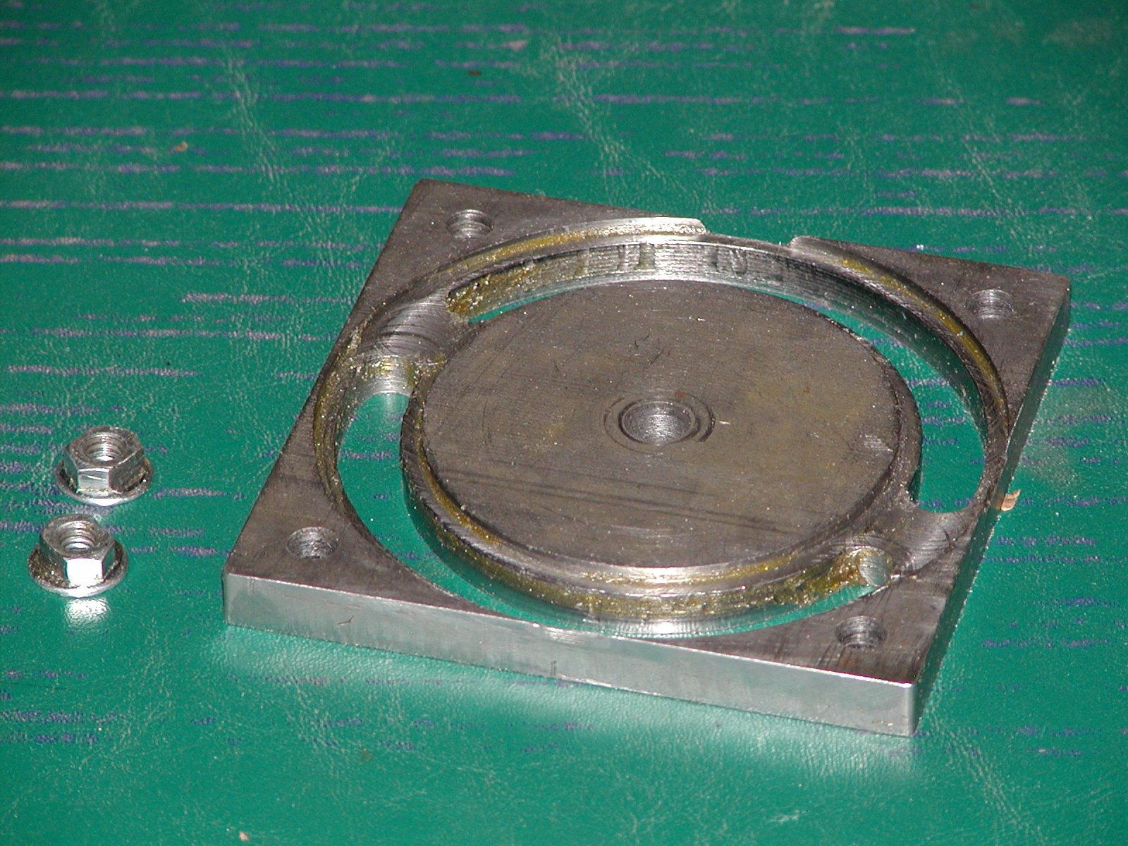
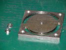
This piece was by far the most difficult to deisgn, but it makes rotating
the secondary slide much easier. The wide base of the nuts slide around the
slots, and are then tightened in position. See below for final assembly.
|
|
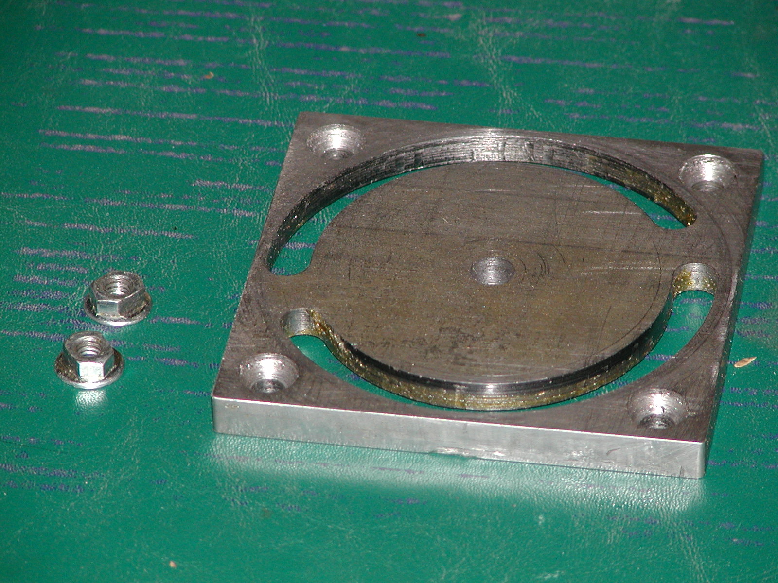
A top view of this plate. This was cut from the same CRS used for the ways
and is 4"x4". The top is smooth with recessed mounting screws to allow
free rotation of the secondary.
|

|
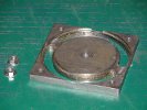
Here is the assembled base slide. The brass washer is used as a
thrust-bearing, and you can see how the notches in the rear plate allow
the slide to move past the end of the base. The T-nuts in the slide are
for mounting the piece with the circular slots.
|
|
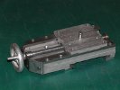
Another view of the assembled slide. You can see the milled-out portion
underneath where the bse slides on the ways plate. All screws are
counter-sunk to ensure smooth operation and limit the areas where
metal shavings could bind the slides.
|
|
Here you can see the assmebly of the feed screw, including the spring
washer used to take up the backlash. The round pieces on the inside are
simply two nuts that were turned smooth, and are tightened gainst each
other. A rolled pin was originally used to fix the position, but I needed
the second thinner nut to set the spacing for how far out the slide
could be moved.
|
|
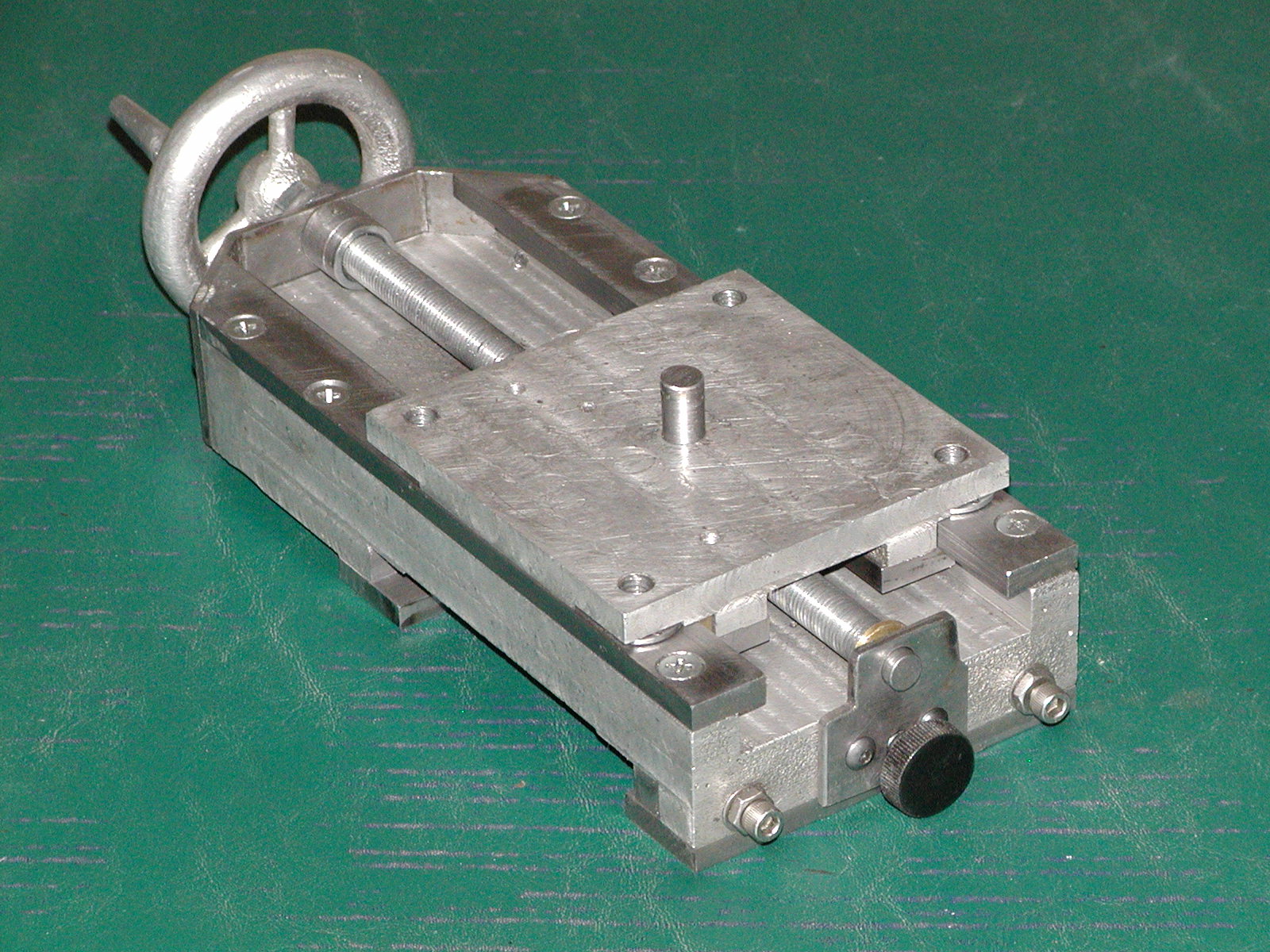
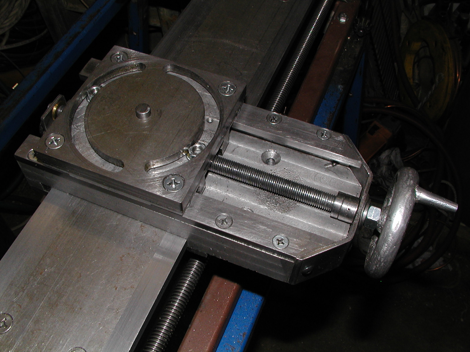
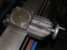
Final assembly of the primary cross-slide. You can see the nuts sitting
in the circular slots. Note that the pivot plate is normally rotated
counter-clockwise 90-degrees, allowing the secondary slide to be
turned from the 90-degree position (facing directly towards the
head-stock), around to about 45-degrees to the left of the primary
slide.
The two tapered holes seen towards the front of the base are used to
screw the cross-slide to the bracket which holds the split-nut to engage
the leadscrew.
|